My friend gave me a X68000 ACE HD which doesn’t power on, and I have been restoring it. The original power supply was dead, so I began reparing it. However, even I manage to fix it, the original unit is designed for Japan’s 100VAC and I am not comfortable using it with the 120V AC standard in the U.S. As a part of the restoration, I’ve also been working on building a new power supply unit compatible with 120V AC, using ATX power supply.
Many enthusiasts have built replacement PSUs for the X68000 using ATX supplies, and my approach follows a similar path.
Components
I purchased the following items:
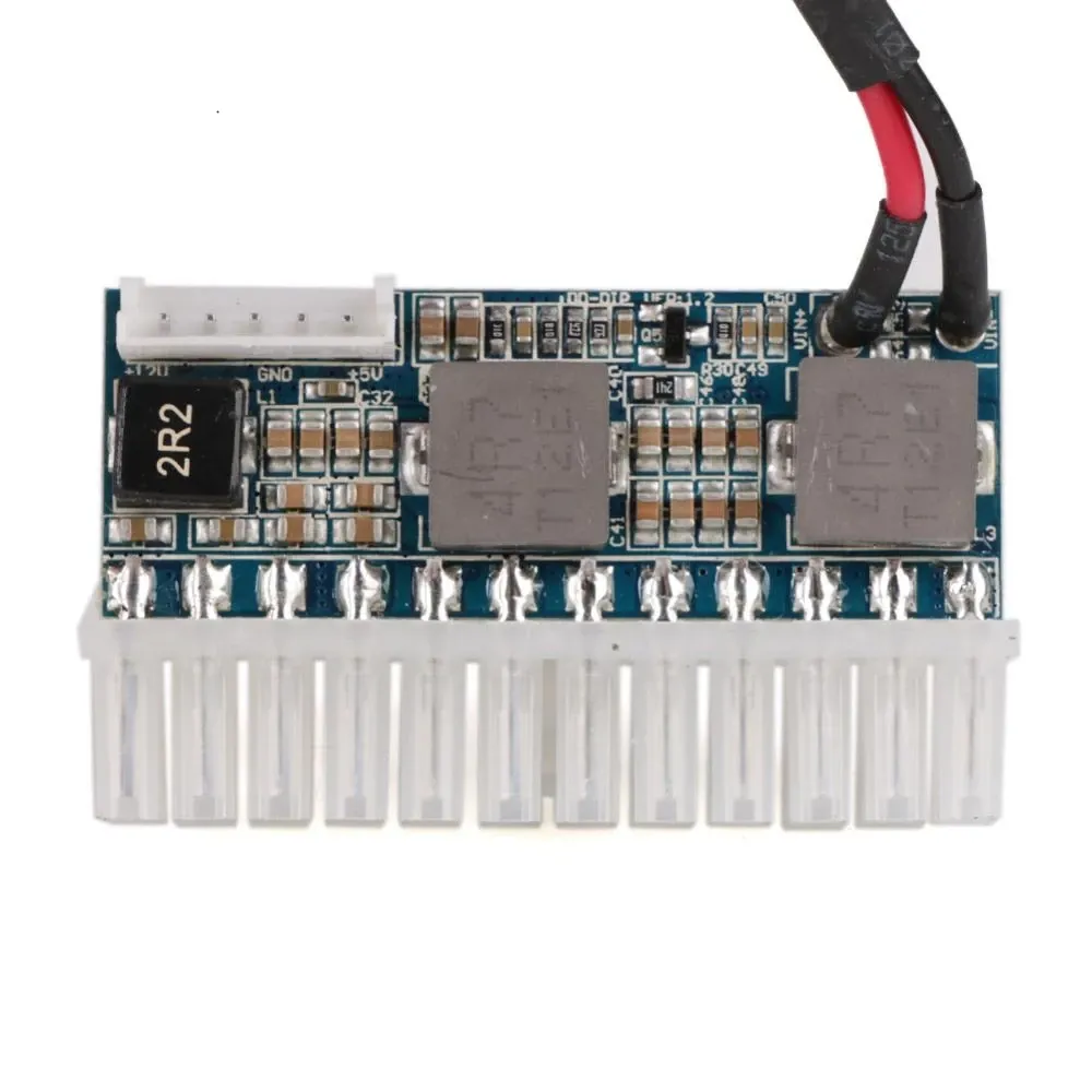
- a Pico ATX
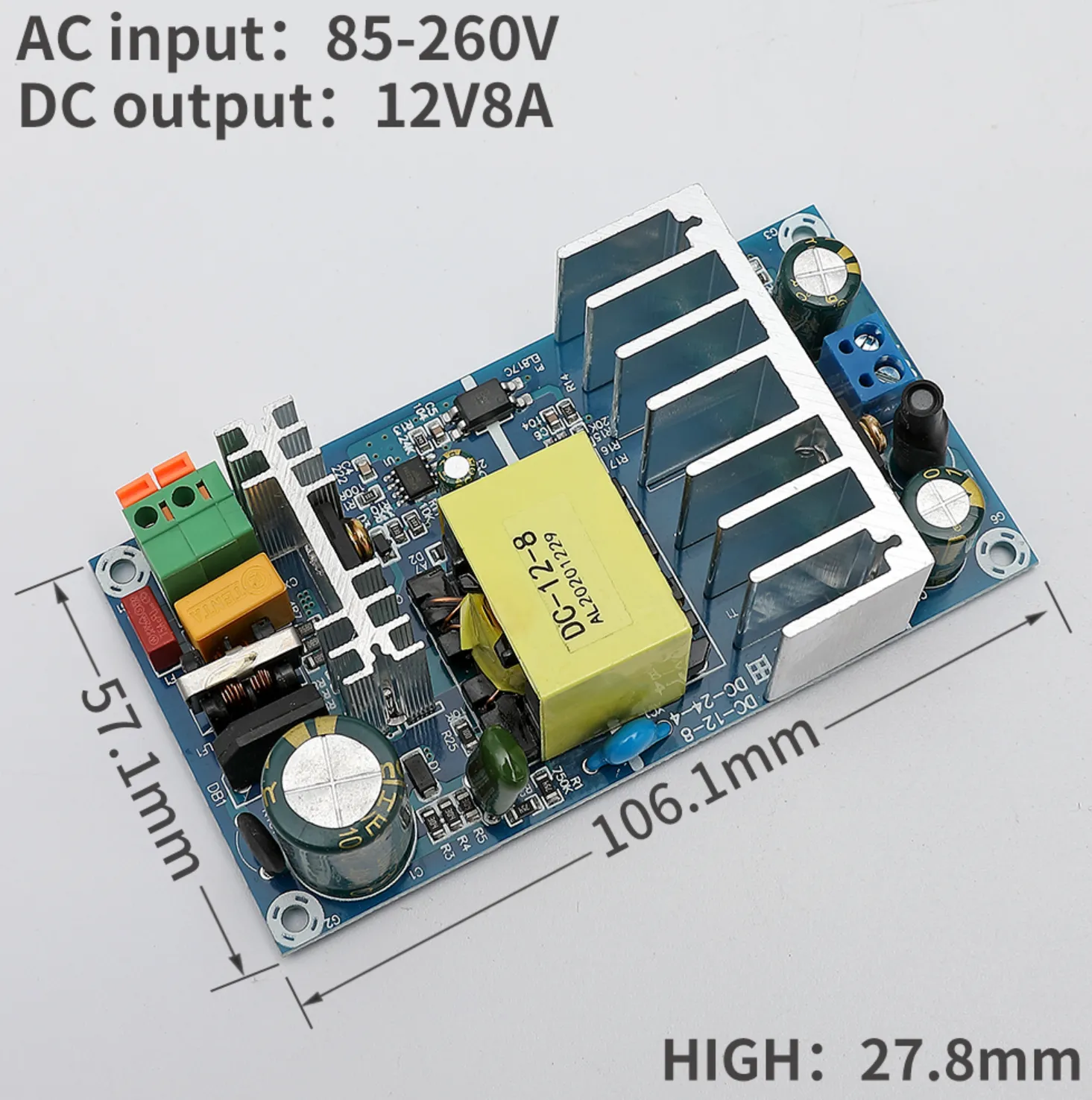
- a 12V8A switching power supply (someone used the exact same power supply)
Also I needed other materials:
- 6 colors of 20 AWG wires
- 2-pin screw connectors
- Various connectors - see below for the details
- Kapton tape
- 74HC04 IC
- Resisters
- Universal board (small)
Chasis
I thought about 3d printing the chasis of the ATX PSU, but I didn’t do it for two reasons:
- The PSU may gets hot and it may catch fire or melt. I am not sure that will really happen, but it was a concern for me.
- The PSU will generates electromagnetic interferance (EMI). The 3d printerd case won’t block the EMI. Again, I don’t know how bad it is. It may not matter.
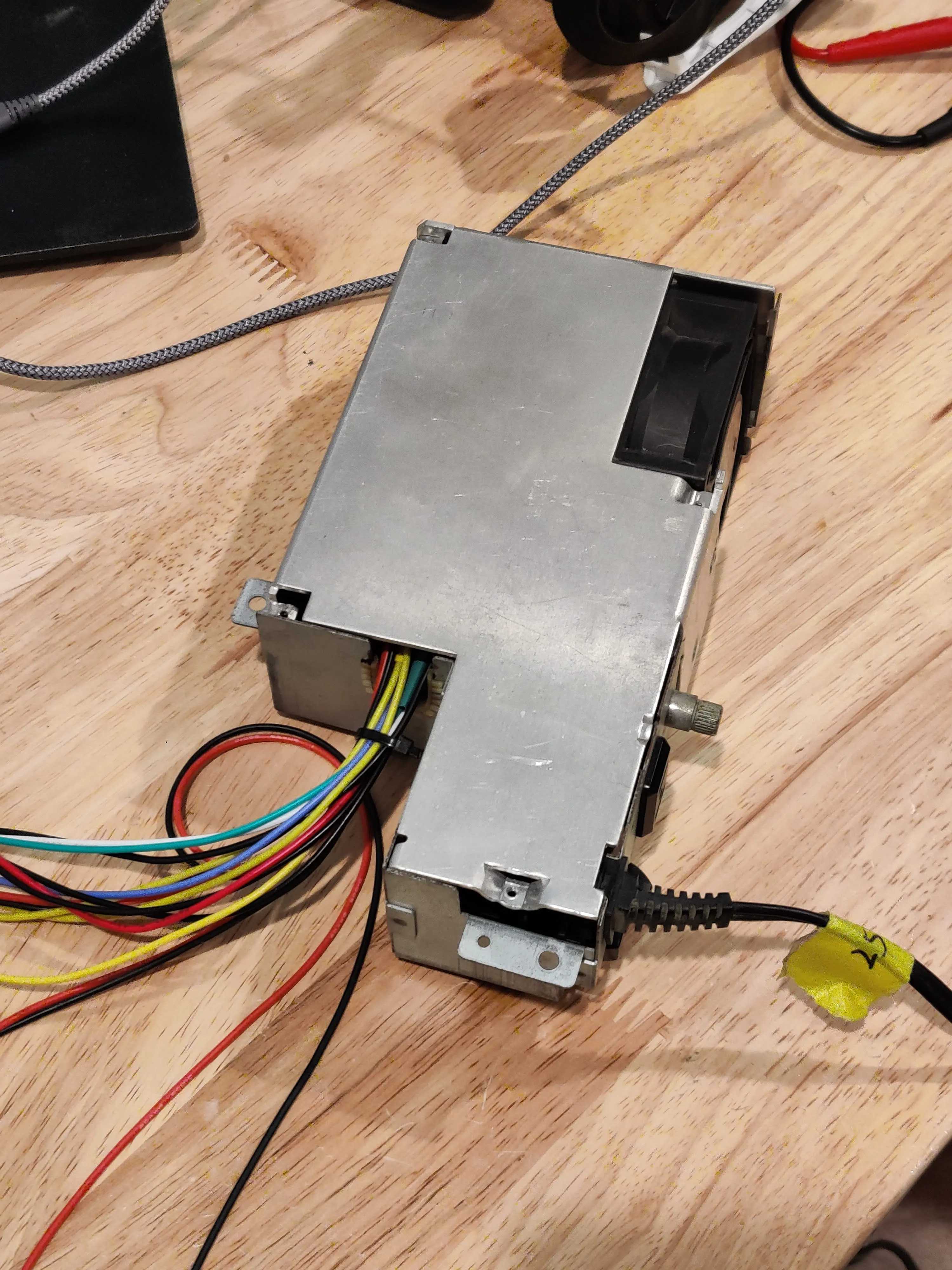
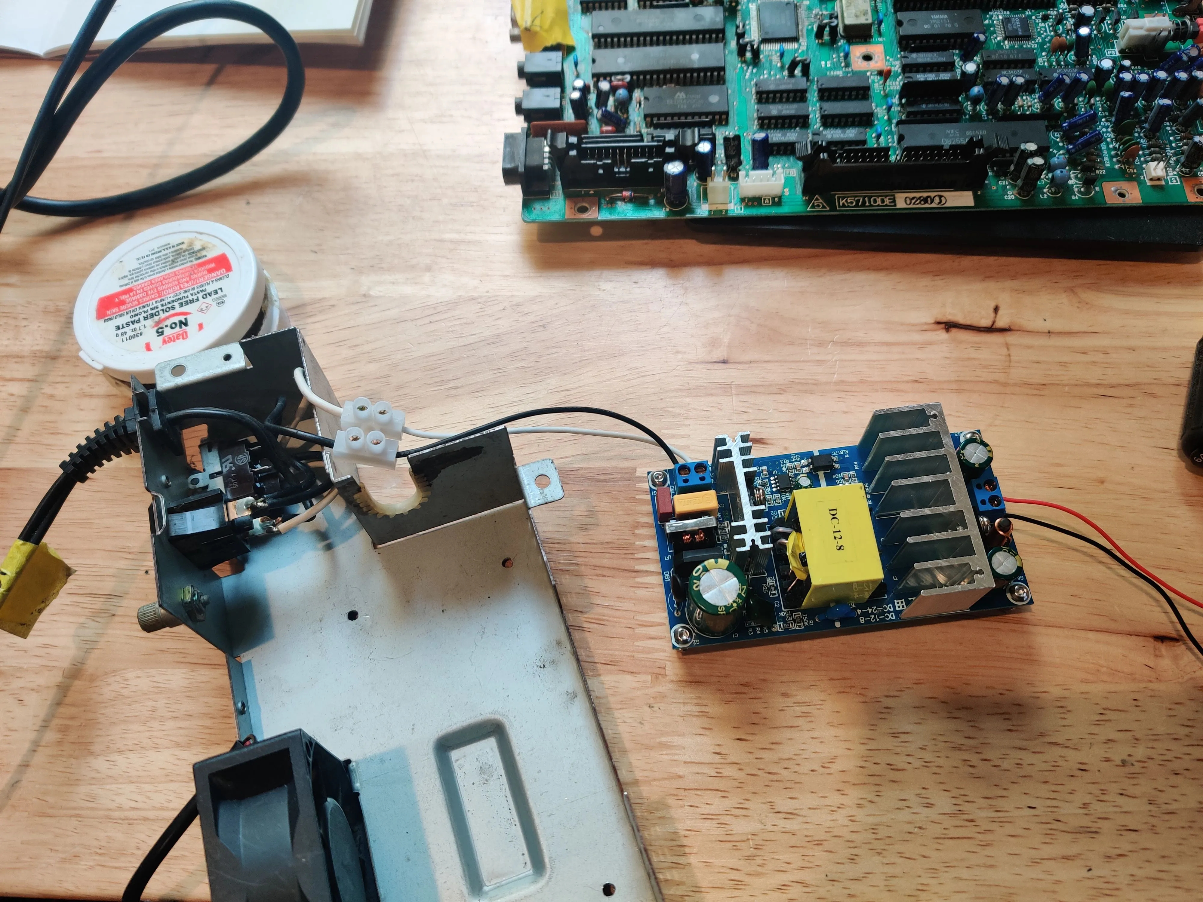
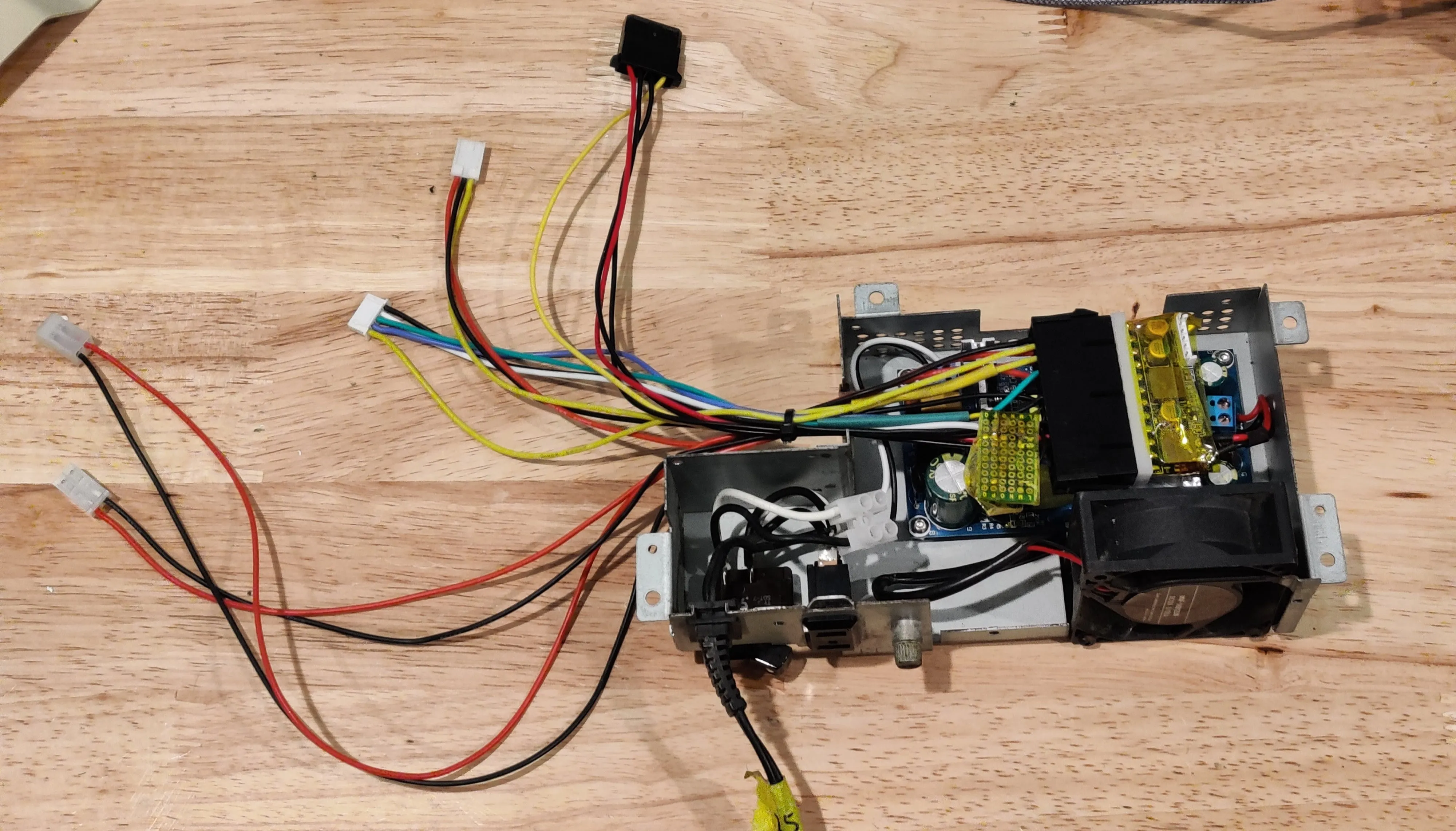
So, I decided to modify the original PSU metal case. I want to keep or re-install the orginal PSU once it is repaired, I preserved all the cables. (Other people cut the wires of the original PSU.)
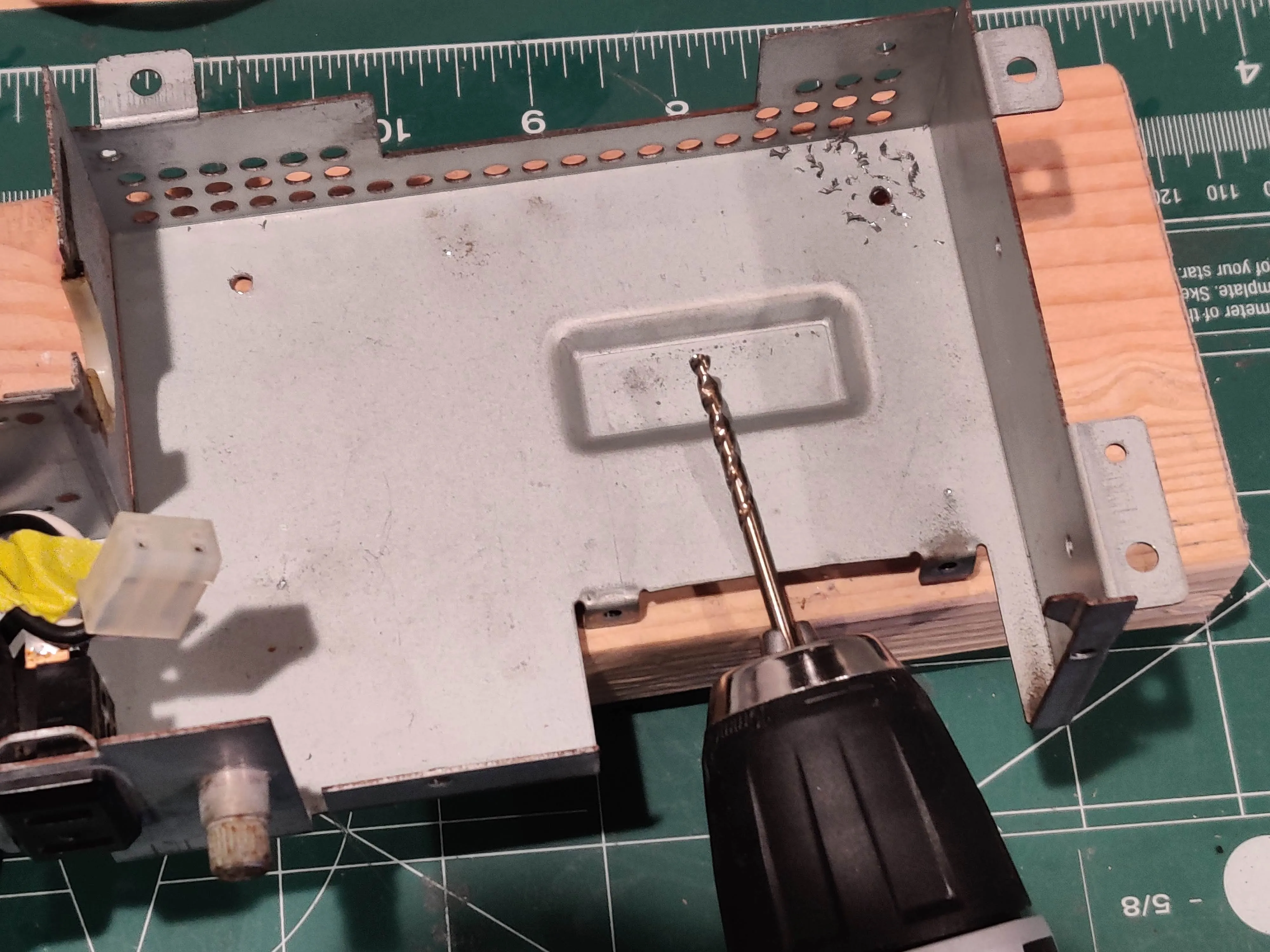
I’ve used M3/8mm bolt and three nuts to mount the PSU. I’ve put two nuts below the PCB so that there’s enough space between the PCB and the metal chasis.
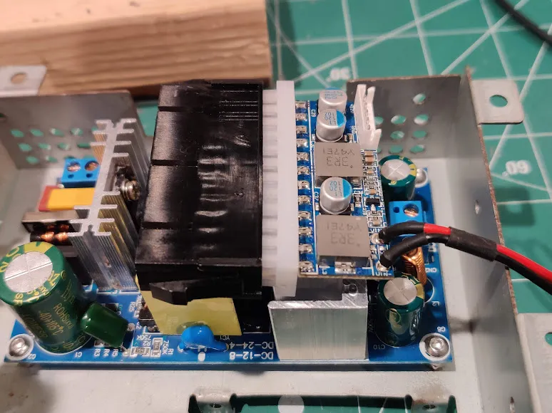
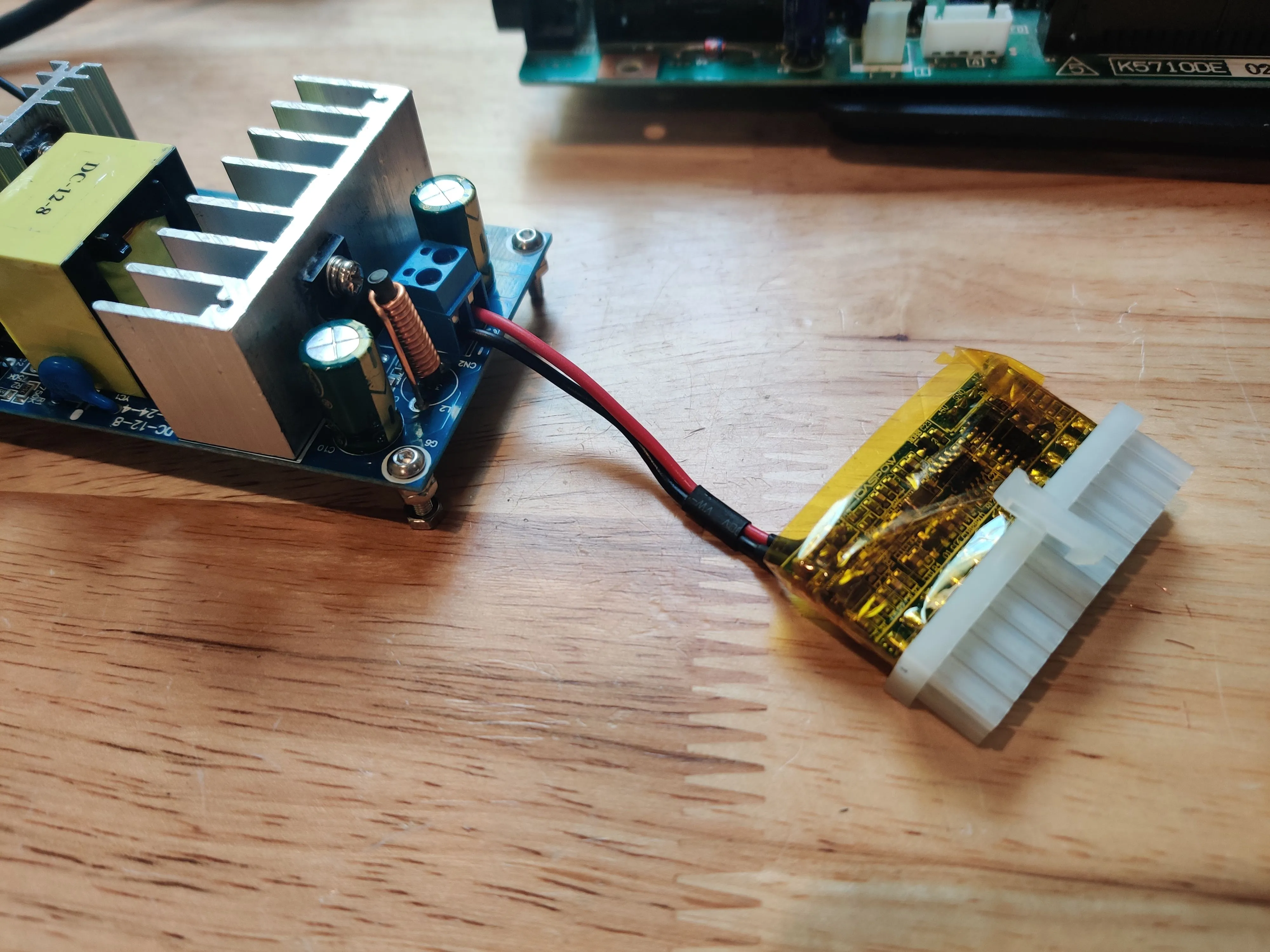
Because the Pico ATX will be on the heat sink, I’ve wrapped it with polyimide tape. It isolates electrically and it can survive around 260C (600F).
I didn’t want to cut the original wires. I’ve used a screw connector to connect the original power wires and the PSU.
Wiring
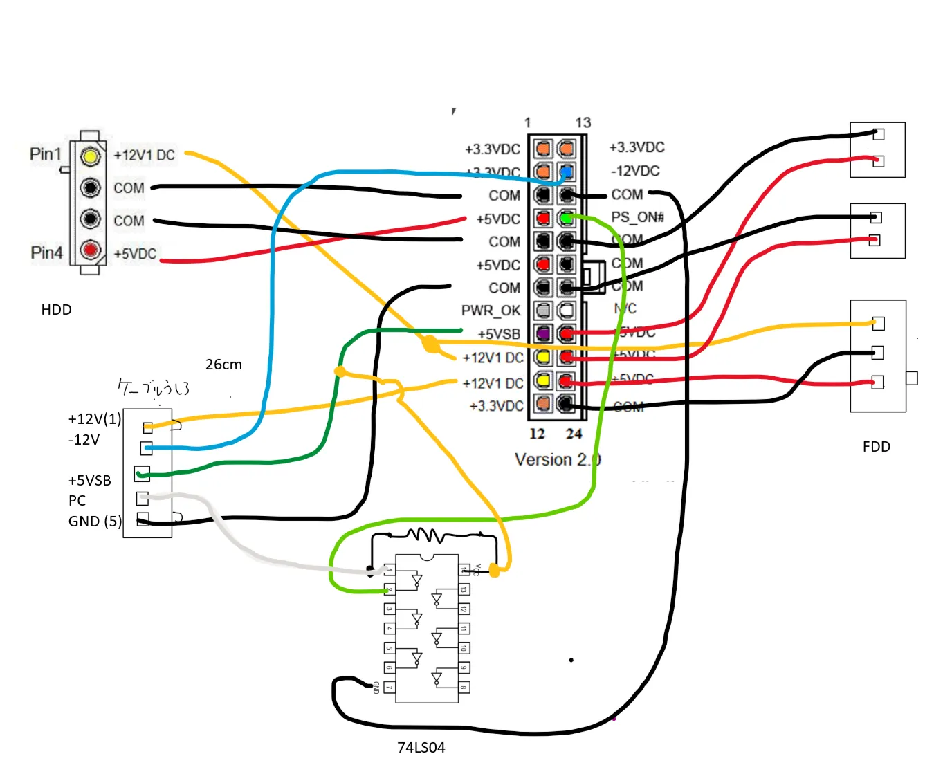
X68000 ACE HD needs +12V, -12V, 5V, and 5V stand-by lines. The handling of power-on is different from PCs, and you need to flip the signal.
Stand-by signal
The ATX power connector has PS_ON pin.
- HIGH: When the PC is turned off.
- LOW: When the PC is powering on, make this LOW to turn on the power supply.
The X68000 has PC signal.
- LOW: When the X68000 is turned off.
- HIGH: When the power button is pressed.
You can find many examples on the internet, and I followed them as well. I’ve created a little board with a 74HC04 and a resister.
When X68000’s PC signal is LOW, the 74HC04’s NOT logic flip it to HIGH (telling the ATX PSU that the machine is off). When X68000 is powered on and the PC signal is HIGH, the 74HC04 flips it to LOW - The ATX PSU is turning on.
X68000 is a 30-year old computer and some of the connectors are obsoleted.
| connector | parts | note |
|---|---|---|
| 2-pin connector (x2) | MOLEX 5195-2 | Use 08701031 SPOX Crimp Terminal 18-24 AWG |
| 3-pin connector | AMP 171822-4 | same as PC’s FDD connector, but 3-pins instead of |
| 4-pin connector | IDE Molex 4 pin female | Typical old HDD connector |
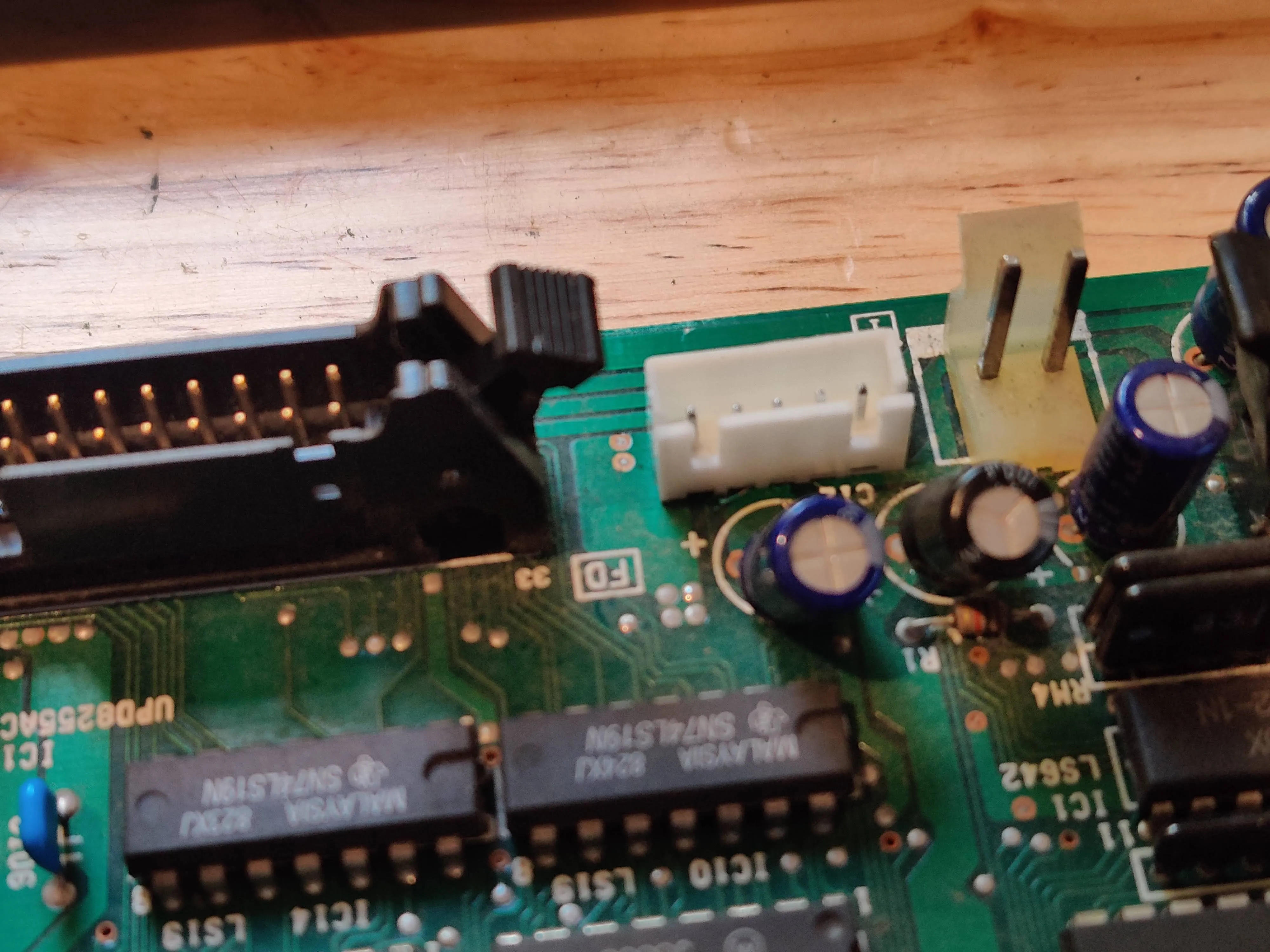
| 5-pin connector | JST XH series (substitute) | I couldn’t find the original one. 2.54mm pitch |
Because I couldn’t find the 5-pin connector, I used JST XH connector for it. I needed to replace the 5-pin female connector of the bottom PCB, as well as the male connector of the original PSU.
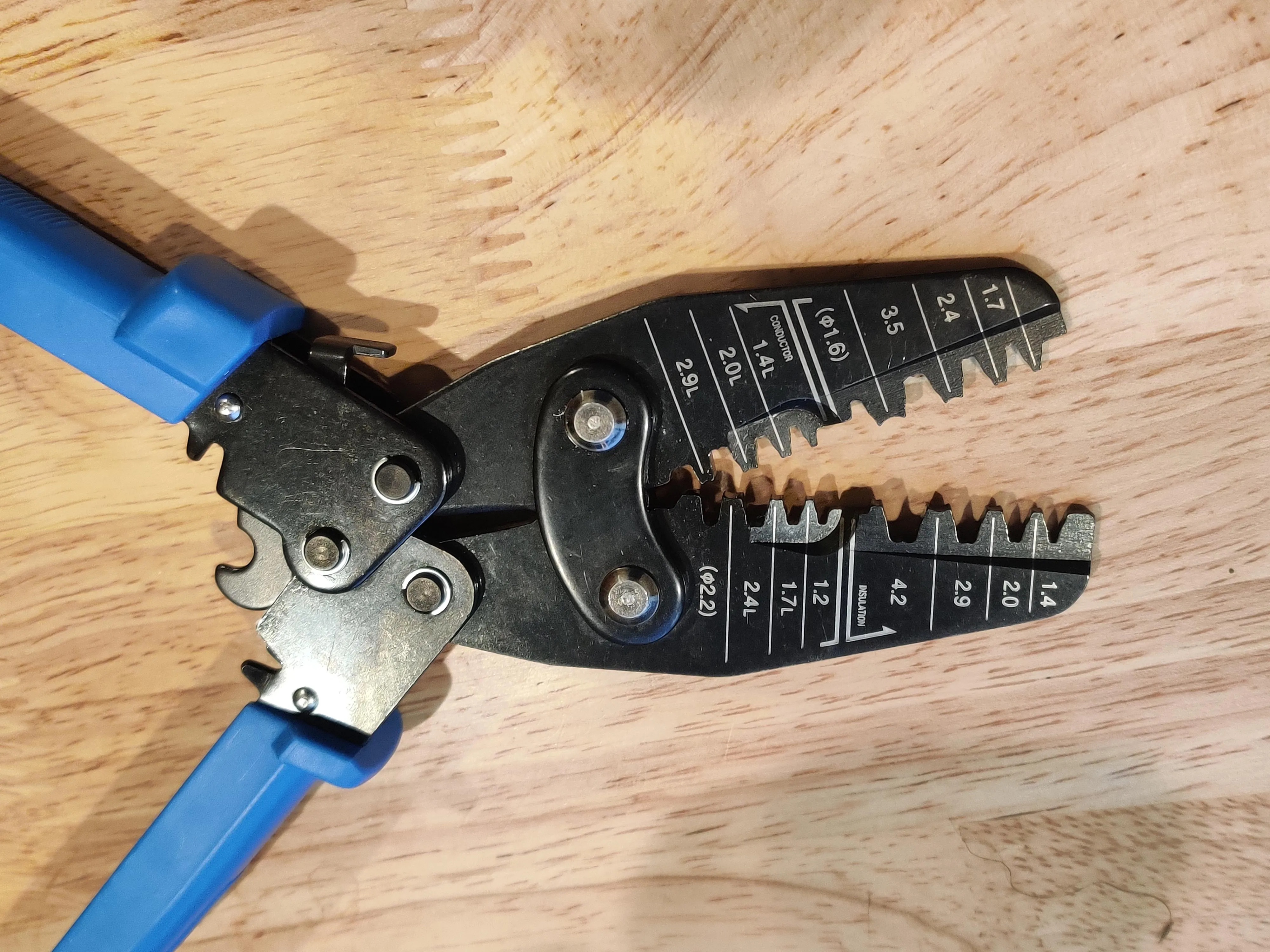
To put connectors to the wires, I needed a clumping tool. I bought Hozan P-707 and it is excellent.
And with putting back the original metal lid back and the work is completed.